


ME-105
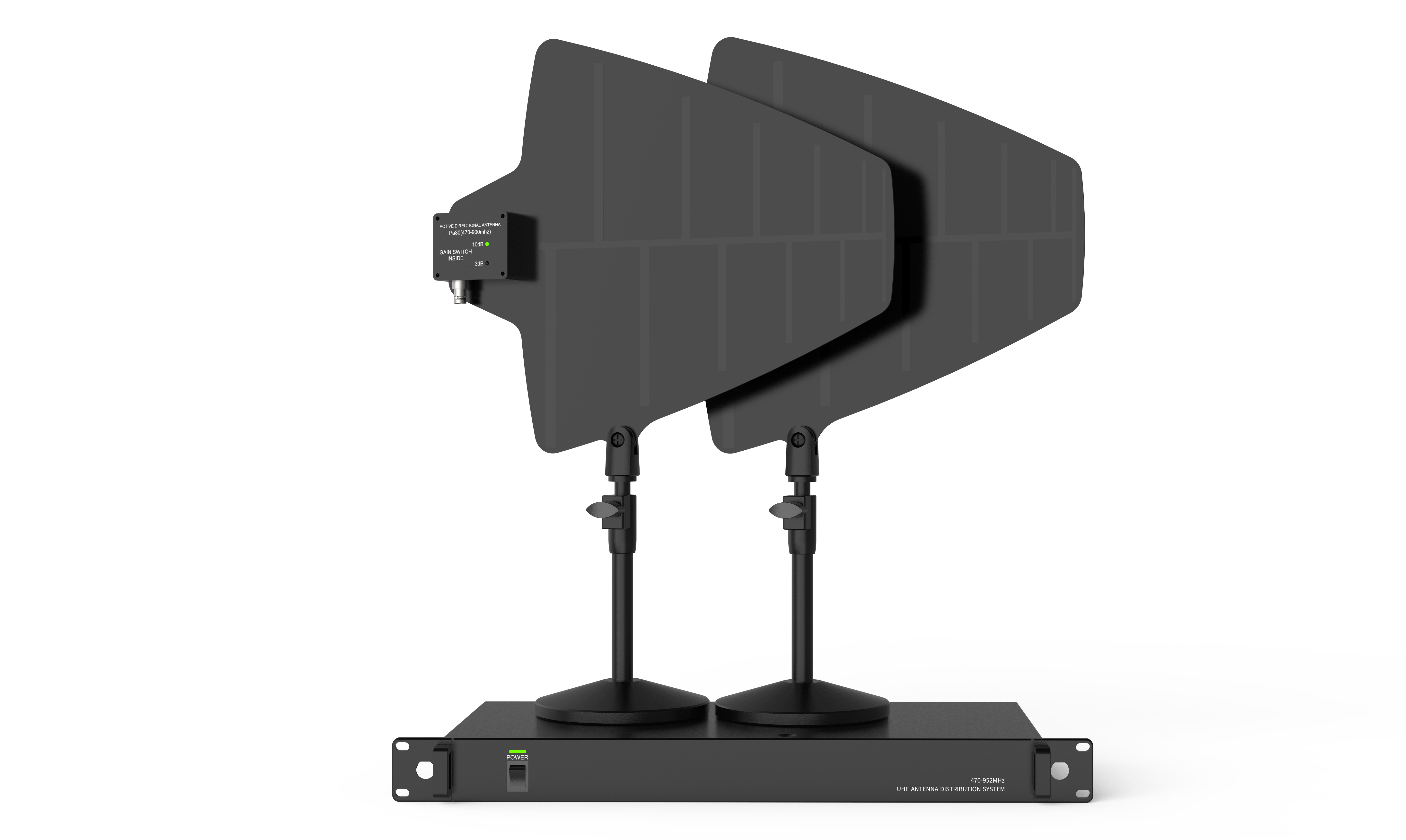
The antenna allocation system allows up to five receivers to use the same antenna group. Simultaneously equipped with power connectors for distributing power to each receiver. The antenna splitter compensates for insertion loss by splitting the antenna input into multiple outputs. The cascade connector can be connected to the fifth receiver or the second antenna distributor.
Category:
- Details
- Function
- Solution
- Parameter
-
- Commodity name: ME-105
The antenna allocation system allows up to five receivers to use the same antenna group. Simultaneously equipped with power connectors for distributing power to each receiver. The antenna splitter compensates for insertion loss by splitting the antenna input into multiple outputs. The cascade connector can be connected to the fifth receiver or the second antenna distributor.
-
1. Automatic frequency search
2. Frequency guide enable
3. Automatic key lock
4. Self-setting name of main unit
5. Squelch door adjustmentUser's guide
1. How to use a handheld wireless microphone correctly
(1) The hand should be held in the middle of the microphone, if it is too close to the head of the net, it will affect the microphone pick-up effect, too close to the bottom antenna position, it will reduce the microphone antenna transmitting efficiency and shorten the use distance.
(2) Adjust the distance between the microphone and the mouth to increase or decrease the high and low tones.
(3) The microphone uses a built-in antenna, so do not get close to large metal bodies, as this will reduce the effectiveness of use.
(4) When the microphone display battery symbol shows one cell, please replace the battery in time, otherwise the microphone will automatically switch off.2. How to use the receiver correctly
(1) Please tighten the antenna of the receiver when using it.
(2) When the receiver uses an omni-directional antenna, the antenna should be 0.5m away from the wall (especially metal bodies).
(3) Avoid placing the receiver at the bottom of the speaker equipment, the receiver should be mounted 1m above the floor.
(4) The receiving range is related to many factors and varies greatly. Better transmission can be obtained without large metal parts blocking in the transmission direction.
(5) If the conditions are not ideal, an extension cable, an external high gain antenna or even an antenna amplifier can be used to achieve a very significant range increase.3. How to use multiple sets of wireless microphones in the same location correctly
(1) When multiple microphones are used in the same place, do not use the same channel and frequency to avoid mutual interference.
(2) When using multiple sets of microphones together, each microphone should be at least 20Cm apart, and under the condition of meeting the transmission distance, low power should be used to avoid intermodulation interference.
(3) When multiple sets of receivers are used together, it is recommended to install high gain antennas, antenna amplifiers and receiving splitters.
(4) If the microphone is set at low power, such as KTV rooms, school classrooms and other occasions are not limited by the number of uses.
(5) If you detect whether each channel is dedicated, you can use the receiver to adjust to the corresponding channel, the receiver display if two frames of signal means that the signal is occupied. -
1. Replaceable microphone head
2. Detachable antenna
3. Detachable foot hardware
4. Sturdy metal housing and high fidelity handheld transmitter
5. Multi-function backlit LCD display for both transmitter and receiver
6. Multi-unit stacking for non-interferenceSystem installation
Installation instructions
Before installing the system, please refer to the Environmental Factors section of this User Guide to eliminate any external or internal sources of interference that may affect the wireless reception of the system.
Placement requirements
(1) A suitable distance should be maintained between the transmitter and receiver, preferably a minimum distance of 2 metres or more.
(2) Obstacles should be reduced between the transmitter and receiver, with no obstacles in sight being the best.
(3) When multiple receivers are used simultaneously, the frequency of the receivers should be kept at a reasonable interval, preferably at a frequency interval of 6MHz.
(4) The antenna of this product is plugged into the two antenna sockets behind the receiver and placed at a vertical angle in the shape of an "L".
(5) Connect the power adapter to the receiver's power input socket.
(6) To ensure the system works optimally and to reduce reflection dead space. Keep the receiver at least 1 metre from the floor and surrounding walls or metal surfaces.System connection
There are two audio outputs on the back panel of the receiver, the XLR open canon socket (balanced) and the 6.3mm socket (balanced and unbalanced). The audio cable is connected to the mixer; it is recommended that if the mixer has an XLR Canon balanced input, it is connected from the XLR Canon balanced output on the back panel of the receiver The mixer has a 6.3mm socket as its input terminal, it is connected from the 6.3mm output terminal on the back panel of the receiver, both sets of outputs can be used simultaneously.
-
Receivers Chassis specifications: EIA Standard 1U Number of channel groups: Dual Channel Frequency stability: ±10PPM Frequency range: 641 – 698MHz Bandwidth: 57MHz Modulation method: FM Reception sensitivity: -105dBm Oscillation mode: PLL phase-locked frequency synthesis Dynamic range: >120dB(A) Distortion: <1% Audio output level: (jack)+6dBV max(±2dB);(XLR)+12dBV max Integrated frequency response: 60Hz~18KHz (-3dB) Electricity supply: DC 12V / 1000mA Output socket: XLR balanced and φ6.3 unbalanced sockets Receivers Frequency range: 641 – 698MHz Bandwidth: 57MHz Frequency stability factor: ±10PPM Maximum frequency deviation: 45KHz Distortion: <1% Oscillation mode: PLL phase-locked frequency synthesis Harmonic radiation: >-60dBC Sound head: Moving coil, cardioid directional Current consumption: 140mA Batteries: AA X 2


FAULT SYMPTOMS AND SOLUTIONS
Below are some common faults and solutions. If you are unable to troubleshoot them, please contact your dealer.
Q:No sound (Status: Receiver RF display not normal)
Q:No sound (Status: Receiver RF display is normal, AF display is normal)
Q:When the transmitter is switched on, the signal is received with a noise or there is interference from an outside voice.
Q:There is noise from the receiver when the transmitter is turned off.
Q:There is occasional loss of sound during mobile use of the transmitter.
Q:Cannot turn on the transmitter
Provide a one-stop solution for your industry and prepare for your choice
Idoson Electronics
Idoson Electronics Co., Ltd
Tel:4006-388-308
Phone:0086 18902580521
E-mail:idoson@mg-tmdt.com
Add:No. 11-4, Shangmao 1st Road, Jiangmen Industrial Transfer Industrial Park, Enping, Guangdong, China
© 2025 Guangdong Idosun Electronics Co., Ltd. Powered by:300.cn SEO